OMS-
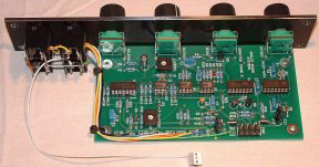
ADSR & VCA (Note the 'rat tail' with 0.1" 3 way socket for the normalised gate signal)
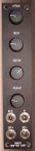
ADSR & VCA Front panel
You can find the UK parts listing in PDF form here.
The standard issue of the ADSR & VCA module has the envelope generator output connected
directly to the VCA CV input, but on my second unit, I have brought the VCA control
voltage input to the front panel to allow external control of the VCA. To keep the
same form factor, though I have sacrificed the OUT-
The modified Schaeffer front panel file is here.
New update:
I have added an LED indicator circuit which gives a visual indication of the envelope level. The LED is fitted just to the right of the 'RELEASE' legend on the front panel.
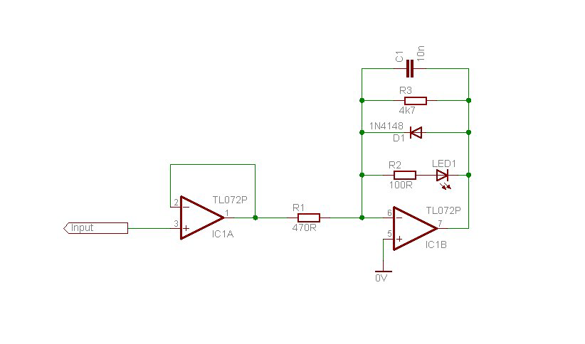
This is based on a standard V/I convertor circuit, but with some modifications suggested
by Tony Allgood. Diode D1 is added in anti parallel with the LED, otherwise the output
of IC1B will be slammed into the +ve rail at every -
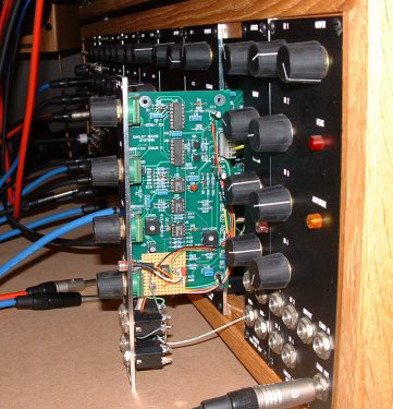
Here's the indicator circuit on a small piece of Veroboard
I have also used a quad version of this circuit (with TL084s) and bicolour LEDs as indicators in my Control 3 module. (Note that with bicolour LEDs, Diode D1 is not necessary.
Page last updated: 4th November 2004