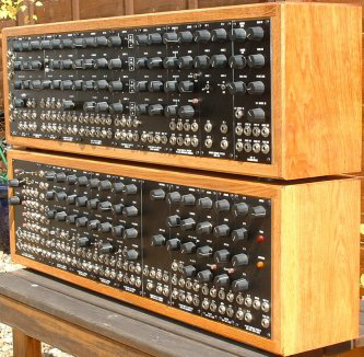
More Cool Pix
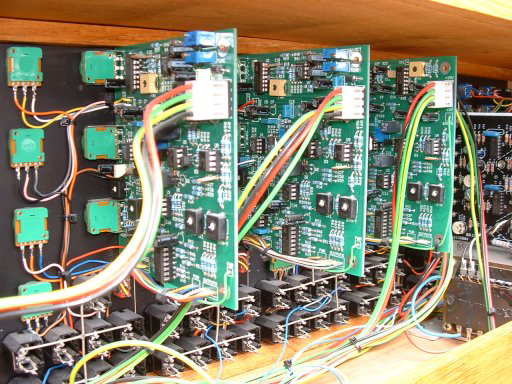
Rear view of the VCOs
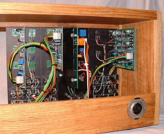
Round the back of the top Cab in an earlier incarnation
Left to Right: SVF, S&H, MOTM SubOctave Multiplexer, Triple VCA
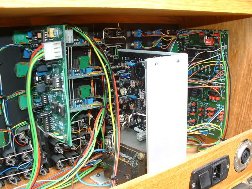
View of the Power One +/-
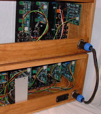
Chunky connectors are used here to bring the power, CV and Gates up to the top cabinet. These are Neutrik 8 Way Speakon Connectors rated at 30A. Note that this photo is from an earlier module arrangement than the photo above it.
The pin connections are as follows:
+1
+15V
-
-
+2
0V
-
Panel (Earth)
+3
+Sense (from +ve out)
-
-
+4
CV
-
Gate
OK, the psu sense implementation is not strictly true sensing because to do that
would need two more pins, as each of the +ve and -
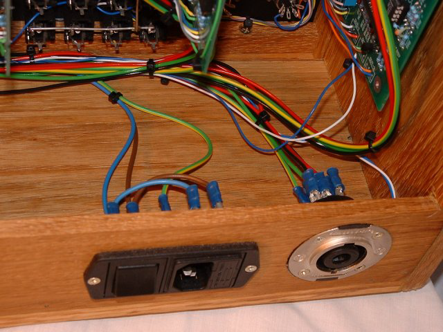
Mains wiring
Page last updated 28th November 2006